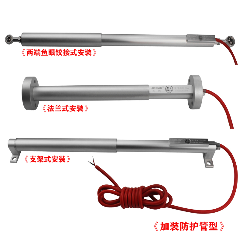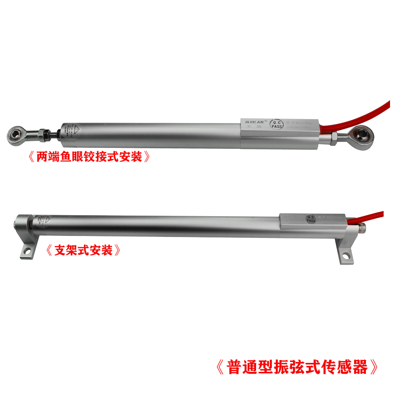


1、 Overview of vibrating wire displacement sensors (crack gauges)
The vibrating wire sensor is a type of non electrical measurement sensor that is widely valued and applied both domestically and internationally. It includes a heat-treated vibrating wire detection element, consisting of a stress relieving spring connected to one end of the vibrating wire and the other end of the sliding rod. As the sliding rod is pulled, the spring begins to elongate and causes an increase in the tension of the vibrating string. The vibration frequency of the steel string also changes accordingly, and the tension is proportional to the elongation of the spring. Therefore, the change in displacement can be achieved by measuring the tension of the steel string, which is the change in the vibration frequency of the steel string.
Due to the fact that the vibrating wire sensor directly outputs the natural frequency signal of the vibrating wire, it has the characteristics of strong anti-interference ability, small influence of electrical parameters, small zero drift, small influence of temperature, stable and reliable performance, vibration resistance, and long service life.


2、 Application fields of vibrating wire displacement sensors (crack gauges)
Vibration string displacement sensors are widely used in engineering projects such as dams, bridges, rocks, concrete, soil, roads, factories, tunnels, underground chambers, and model tests to monitor the displacement, settlement, deformation, cracks, and other changes in long-term relative displacement of structural objects.
3、 Technical parameters of vibrating wire displacement sensor (crack gauge)
| Model | MLZX-XXXmm |
| Testing Range | 12.5, 25, 50, 100, 150, 200, 250, 300mm |
| Resolution ratio | 0.025%FSR |
| Linearity | 0.25%FSR |
| Temperature and drifting | <0.05%FSR/℃ |
| Stability | <0.2%FSR/Year |
| Frequency range | 1500-2800Hz |
| Temperature range | -40 ~ +60℃ |
| Coil resistance | 230Ω±10Ω |
| IP Rate | IP67 |
| Cable Type | 2-core |
4、 Naming rules for vibrating wire displacement sensors (crack gauges) products
![1708926767746147.jpg 1699958314146694[1].jpg](/uploads/image/20240226/1708926767746147.jpg)
5、 Installation dimensions of vibrating wire displacement sensor (crack gauge) (unit: mm)

6、 Precautions for vibrating wire displacement sensors (crack gauges)
● This instrument should operate within the rated measurement range.
● When installing instrument cables, try to keep them away from electrical interference such as engines, transformers, spot welding machines, power cables, motor engines, etc. Cables are never allowed to be buried underground or transmitted together with AC power lines! Otherwise, the cable will sense electrical interference signals of other frequencies, which will cause trouble for the instrument to obtain stable readings.
● When extending cables according to on-site needs, attention should be paid to ensuring reliable waterproof sealing at the joints.
● The instrument should be handled and installed with caution, avoiding violent vibrations. To avoid any mechanical damage or deformation to instruments or components, it is important to protect the sensors, measuring rods, and their connecting ports from damage and deformation
● The instrument cable can reach up to 1000 meters (to be purchased separately). The user did not specify when placing an order, and all wires were wired to a length of 2 meters before leaving the factory.
● When the instrument has not been used for more than 12 months, it should be recalibrated before use.
7、 Detection report of vibrating wire displacement sensor (crack gauge):


1、 Overview of the acquisition module of the vibrating string crack meter:
The Miran RS485 vibrating wire sensor acquisition card module can convert the natural frequency signal of the vibrating wire sensor into displacement through RS485 output via MODBUS-RTU protocol, and achieve user calibration of different vibrating wire sensors through serial port commands. After the user completes the temperature coefficient, linear coefficient, starting point, and temperature calibration operations, linear output is achieved based on the calibration coefficient, and the parts outside the calibration are considered dead zones.
2、 Explanation of the vibration string crack meter acquisition module:
The vibrating string acquisition module is designed specifically for environments with severe interference. In daily work environments, analog signal transmission is prone to interference. The quality of transmission wires, the configuration of surrounding equipment, and the installation environment of wires can greatly affect the transmission of analog signals.
This module is used in conjunction with the Miran vibrating string displacement sensor RS485 digital signal output product. The sensor triggers self oscillation through the excitation signal transmitted by the module, and then the module collects the self oscillation frequency of the sensor, decodes it to obtain displacement data, and outputs real-time signals to the PC end through RS485 of the module.
There is a dedicated power supply voltage filtering and stabilization system inside the module. Provide a comprehensive power supply solution for displacement measurement. Solved the unstable readings caused by the unstable voltage interference caused by the shared power supply on the machine.
This solution does not require any modifications to existing equipment configurations, such as control computers and wiring, and the resulting displacement readings are more comparable to those obtained using fieldbus.
3、 Characteristics of the vibration string crack meter acquisition module:
● Wiring terminals, with plug and unplug connectors for easier use.
● Isolate the power supply to prevent interference and ensure greater safety.
● The vibrating wire acquisition card is used in conjunction with the vibrating wire sensor, and can be replaced with vibrating wire sensors of different ranges for calibration at any time.
4、 Precautions for the acquisition module of the vibrating wire crack meter:
★ LED Description: When the module outputs normally, the LED lights alternate between red and green colors.
★ Configuration Description: The module needs to be consistent with the configuration of the vibrating wire sensor (baud rate: 9600, data bits 8, stop bit 1, no verification, sensor address: 01Hs)
★ Calibration instructions: If the user accidentally enters the calibration mode during operation, simply keep the position of the displacement sensor unchanged and calibrate the starting and ending points at the same position. If the distance between the calibration starting and ending points is too small, the module will determine that this calibration is invalid.
5、Product Selection:

6、Product Parameters:
| Power Supply | 12-24V |
| Working Current | <20mA (24VDC) |
| Frequency measurement range | 400~6000HZ |
| Signal Output | RS485 |
| Resolving power | ≤0.1HZ |
| Communication Protocol | Modbus-RTU |
| Communication distance | RS485 communication distance<1200 meters |
| Installation method | Fixed installation, rail installation optional |
| work environment | Temperature: -30~+85 ℃, humidity: 0~85%, no condensation |
7、 Wiring diagram:

8、 Installation size:
