


1 Principle and overview of fixed inclinometer/inclinometer:
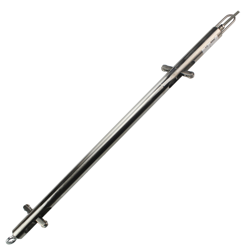
The fixed inclinometer is a fixed inclinometer developed by our company based on high-precision six axis sensors combined with single-chip embedded systems. It is used to observe the relative horizontal biaxial tilt angle of slopes, foundation pits, railways, etc., and combined with automatic real-time monitoring systems, it can also be suitable for long-term monitoring of landslide geological activities. The multi-level setting of drilling can measure the inclination angle of each depth, convert the inclination angle into displacement, and is suitable for the deformation variables of concealed parts that are difficult to observe by conventional measurement methods.![1708929777599201[1].png](/uploads/image/20240227/1709019558841770.png "1709019558841770.png")
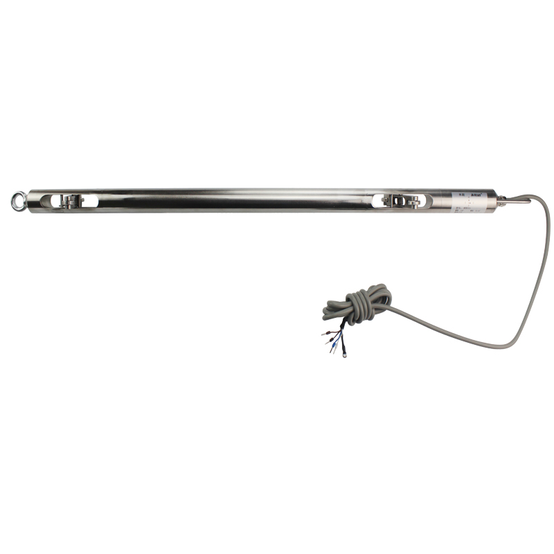
The fixed inclinometer is composed of an electronic compartment (high-precision angle sensitive components and chipset), as well as external stainless steel components, pulley components, etc. An external four core shielded wire leads out. Usually, the installation of fixed inclinometers also requires the installation of accessories, such as inclinometers, stainless steel wires, lifting rings, etc., which need to be configured reasonably according to the on-site situation.![1708930027219730[1].png](/uploads/image/20240227/1709019570103005.png "1709019570103005.png")
2 Technical parameters of fixed inclinometer/inclinometer:
Item | Parameter |
Voltage Supply | +9V--28VDC |
Working Current | 14mA(+24VDC) |
Working Temperature | -20℃--80℃ |
Testing Range | XY Dual Axis ±60° |
Resolution ratio | 0.01° |
Accuracy | ±0.05° |
Output Signal | RS485 |
Protocol | Modbus—RTU |
Guide wheels distance | 500mm |
Cable Length | 2m default |
Wiring Definition | Brown:Supply(+) Black:Supply(-) Blue:458(A) White:485(B) |
3 Product Naming Rules

Under actual installation conditions, the direction of the guide wheel (i.e. the X-axis direction) should be installed towards the expected tilt direction. After the inclinometer is placed in the designated position of the inclinometer tube, the initial angle value needs to be determined. After installation, read the current angle value of the inclinometer. After the data stabilizes, take the average of the current position angle as the initial angle value of the sensor, denoted as Angle_X0, Angle_Y0. Afterwards, the angle values of all sensors are calculated based on this initial angle value.
The horizontal displacement of the initial value in the X-axis direction is represented by DX0, the displacement in the y-axis direction is represented by DY0, and the overall displacement is represented by D0. The angle data measured by sensors, Angle_X and Angle_Y, are calculated using a trigonometric function at the gauge length L (i.e. the wheelbase before adjacent sensors) to obtain the horizontal displacement at the measured gauge length. The displacement direction is based on the sign of the angle data measured on the X and Y axes, with+indicating positive direction and - indicating negative direction. In practical use, data analysis is conducted based on relative displacement, which refers to the displacement of each measurement point relative to its initial position. Reference for displacement calculation method :
Displacement in initial direction of X-axis : DX0 = L*sin(Angle_X0)
Displacement in initial direction of Y-axis : DY0 = L*sin(Angle_Y0)
Overall displacement at initial position : D0 = (DX0²+DY0)½
Horizontal displacement in the X-axis direction : DXn = L*sin(Angle_Xn)
Relative displacement in the X-axis direction : △DXn = DXn - DX0
Horizontal displacement in the Y-axis direction : DYn = L*sin(Angle_Yn)
Relative displacement in the Y-axis direction : △DYn = DYn - DY0